4-Rotor Flying Robot
The OU 4-rotor flying robot is based on the Silverlit
XUFO. We have added an Atmel Mega8 microcontroller
equipped with a Devantech compass. This
microcontroller overrides the RF receiver of the XUFO and provides its
own pulse-width-modulated control signal. Because we insert this
signal immediately after the RF stage, the functionality of the XUFO
gyroscope is left intact.
|

|
Physical Interface
From the Power Supply
We are using RadioShack 13V ~10A power supplies. These are sitting on
the tables next to the helis (as many as two helis will be connected
to a given power supply). For each heli, there are two
connections:
- Power to the craft itself
- +5V regulated power for your off-board control circuit. Note
that the regulators that we are using can become quite hot to
the touch (but not hot enough to burn).
In both cases, ground is black and power is red.
To/From Heli
The heli has a pair of 3m length cables attached to it. The first
cable provides power to the craft (as described above).
The second cable provides the bidirectional serial interface as a
2-pin connector. The pin assignments are as follows:
- Orange: transmit from heli
- Purple: send to heli
Note: this serial interface uses +5 and 0V to encode the serial data.
If you are directly connecting the heli to a device that uses the same
encoding (such as another
Atmel mega8 microcontroller), then the connection can be made
directly. However, if you are connecting to a standard RS232
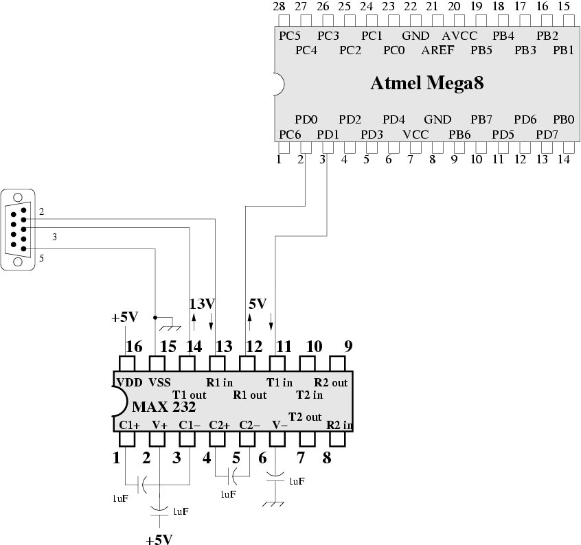
interface (e.g., a DB9 serial port on a desktop/laptop computer), then
you will need a level shifting circuit (see
an
example circuit).
Serial Protocol
Querying the Compass State
The host transmits:
c
The heli responds with:
cDDDD\n\r
Where DDDD is a 4 digit decimal number that gives the
orientation of the craft in tenths of a degree. Note that "\n" is the
character '\n', not the characters '\' and 'n'.
Commanding the Heli
Roll.
The host transmits:
rDDD\n\r
Where DDD is a 1-3 digit decimal number that determines the
current roll command. Values outside of the range 1-255 are ignored.
A value of 128 corresponds to "no roll"; higher values correspond to
positive roll (rotation about X in the figure).
Pitch.
The host transmits:
pDDD\n\r
Where numbers larger than 128 correspond to positive pitch (rotation
about Y)
.
Yaw.
The host transmits:
yDDD\n\r
Where numbers larger than 128 correspond to negative yaw (rotation
about Z).
Throttle.
The host transmits:
tDDD\n\r
Where the rotors will begin to spin around values of 80. Values in
the vicinity of 140 are sufficient to hover.
Emergency.
The host transmits:
e
This command immediately sets roll, pitch, and yaw to neutral, and
throttle to low.
Debugging Commands
These commands are most useful when you have attached the serial
interface to a terminal or a computer executing a terminal program
(e.g., kermit or hyperterm).
The host transmits:
s
The heli responds with a list of the actual signals being presented to
the heli (in units of 1/2 usec). For roll, pitch, and yaw, 2000 is
neutral.
The host transmits:
S
The heli responds with a list of the current calibration potentiometer
states (in units of 1/2 usec).
Powering On
Step 1: Main Power
- Turn on the main power supply.
- This will power the Atmel control circuit and your off-board circuit.
- LED 0 (red) will flash for a brief amount of time at power
up. This LED will also flash as serial commands are
received. However, if this LED is ever on persistently,
this is indicative of a system error and should be
reported immediately.
Step 2: Craft Power
- If you are just starting: check to make sure that the
calibration potentiometers (described in step 3 below) are in
the center
of their range.
- Level the craft as best as possible (the current orientation
will determine the "neutral orientation" over the next few
steps). You can do this either by
placing the craft properly on the ground or by holding it.
- Turn on the craft power (see image below). This is the switch
located on the heli itself.
- LED 1 (green or yellow) will flash continuously after this point.
- You will hear the mechanical gyroscope spin up. Once this
process is completed, you will see the LEDs mounted to each of
the rotor motors flash in a circular pattern.
- You may then issue commands to the heli. Note that if you
issue a throttle command before the gyro is spun up, it will
only take effect after the gyro is ready.
- If the craft is ever pitched or rolled beyond a relatively
narrow window (~ +/- 20 degrees), the gyro will spin down. In
this case, or if you ever want to completely recalibrate the
neutral orientation, then power down the craft and restart this
sequence.

Step 3: Tuning the Neutral Position (Optional)
Once the gyro has been spun up, you have the option of turning the
neutral position for the pitch, roll, and yaw dimensions. By "neutral
position", we mean zero pitch and roll (and hence, no tendency to
translate) and zero yaw (no acceleration about the yaw dimension).
The procedure is as follows:
- Send neutral commands via the serial interface for each of
pitch, roll, and yaw (128 in all cases).
- Holding onto the craft from its base, bring throttle to a level
that produces a significant amount of thrust (~120 will work).
- Using a small screw driver, you can then adjust the pitch,
roll, and yaw potentiometers until all three are truly
neutral.
Safety
Safety for the Human
Although the rotor blades are moving at a high rate of rotation, they
have very little momentum. As a result, placing one's finger in the
path will hurt, but not damage the finger. (Besides huring) since
this can damage the craft, however, this is not suggested.
For those who will be holding onto the craft during testing (while the
rotors are spinning), safety goggles will be provided.
Safety for the Heli
Although the crafts are rather robust to abuse, it is important to
take steps to protect them. In general, it is bad to run the crafts
against the ground or the ceiling.
- Early in the software testing process, a team member should hold onto
the bottom of the craft.
- You can stabilize the craft by holding onto the power/serial
cables. In particular, this is useful to ensure that the craft
never goes too high. However, be ready for sudden altitude
drops.
- Be conservative with the throttle.
- Throttle commands between 70 and 140 should be
sufficient for our purposes.
- Avoid changing the throttle suddenly. In particular, if
you are automatically landing the craft, slowly reducing
the throttle.
- Because of the power/serial cables, as the craft
increases its altitude, it will carry more weight. This
means that within a reasonable range of throttle
commands, the height is self-regulating. In fact, the
equilibrium height of the craft is monotonically related
to the throttle command.
- For our projects, you will not need to change the roll and
pitch commands away from 128 (neutral).
- Implement and test incrementally. Convince yourself that each
piece is working properly before you go onto the next step.
- If something unexpected happens, immediately cut the
power at the power supply.
- Do not leave the throttle up for more than 2 minutes at a
time. Give the craft a break to allow the
motors to cool (this will extend the life of our motors).
fagg [[at]] ou.edu
Last modified: Tue Mar 24 00:13:28 2009